Introduction
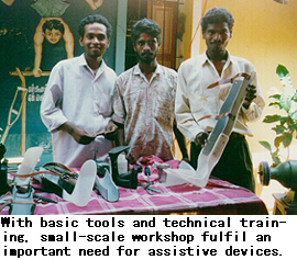
In many developing countries of the Asia-Pacific region, information on methods of producing assistive devices is not easily accessible to users or to agencies and organizations which could produce those devices. This supplement contains a selection of technical details pertaining to prostheses and orthoses, wheelchairs, other devices for people with mobility difficulties (e.g., crutches and handgrips), and hearing aids. The selection indicates that small-scale workshops which have the basic tools and skills could go a long way towards helping to meet the need for appropriate devices, especially in rural communities.
Those who wish to embark on the production of the devices are advised to contact directly the sources cited (see also Directory of Producers) for full technical details.
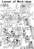
Layout of Work-shop
Prostheses and Orthoses
A. Basic tools and machines required in a small workshop
Below is a list of basic tools and machines required in a small workshop for the production of prostheses and orthoses.
- (a) Woodworkers' vises;
- (b) Woodworking gauge;
- (c) Carpenter tool set including auger/ hand drill;
- (d) Chisels of different types and sizes;
- (e) Pipe vises;
- (f) Measurement table;
- (g) Mallets;
- (h) Caliper dividers and compasses;
- (i) Pliers;
- (j) Shoemaker anvil;
- (k) Punch to break eyelet (for shoe making);
- (l) Scissors for leather work;
- (m) Metal cutting scissors;
- (n) Files of different sizes;
- (o) Spanner set;
- (p) Bench drilling machine and drill bits;
- (q) Belt and disc sander;
- (r) Hand shearing machine;
- (s) Grinder;
- (t) Leather sewing machine;
- (u) Band saw;
- (v) Soldering iron;
- (w) Plastic cutting saw;
- (x) Electric oven;
- (y) Vacuum forming machine.
B. Basic materials required for production
The following is a list of basic materials required for small-scale workshop production of prostheses and orthoses.
- (a) Aluminium sheet and strips;
- (b) Steel sheet and strips;
- (c) Orthoses components, including knee joints, side bars and stirrups;
- (d) Copper and aluminium rivets;
- (e) Screws and nuts;
- (f) Buckles;
- (g) Velcro loop and hook;
- (h) Sponge and foam;
- (i) Wood;
- (j) Plaster of Paris (POP);
- (k) Plaster of Paris bandage;
- (l) Polyester resin;
- (m) Prosthesis components, including prosthetic feet, ankle adapters and knee joints;
- (n) Belt stitching thread;
- (o) Adhesive-like rubber solution;
- (p) Stockinettes;
- (q) Polypropylene sheet.
C. Notes on making a patellar-tendon-bearing (PTB) prosthesis
In a regular PTB prosthesis, the shanks are constructed mainly of wood, usually willow. The shank houses the socket which is most commonly made of polyester resin. The shank is shaped carefully to conform to the external shape of the normal leg. The shank is often covered with a thin, flesh-coloured polyester laminate.
For making a socket, a negative plaster cast of the stump is taken by wrapping it with a POP bandage. A positive mould is made by filling the negative mould with POP and water and then allowing it to harden. A fabric (stockinette) is pulled over the positive mould and a plastic resin, usually polyester, is poured into the stockinette so that a fabric-reinforced plastic laminate of the shape of the stump may be obtained. In order to improve the flow of the resin, it is common to use a vacuum machine. The socket thus made may then be fitted into an all-plastic exoskeletal prosthesis, or a pylon in an endoskeletal prosthesis. The pylon in the latter case may be a tube made of aluminium, titanium, steel or carbon fibre-reinforced plastic. The endoskeletal prosthesis is then covered with a foam.
With the availability of polypropylene of the right grade, a rapid shift is taking place from polyester sockets to polypropylene sockets. A polypropylene sheet is heated in an electric oven at 180 degree celsius till the sheet becomes POP mould. There are two methods of draping:
- The bubble drape technique, in which the bubble in the softened sheet drapes a strong socket and no welds are required in the socket. However, it is expensive since special equipment must be used (e.g. special vacuum lines) and a thick sheet of polypropylene is required to obtain the same thickness all over the socket. The thickness of the starting sheet is usually 12mm.
- The wrap drape is strong and cheaper. A thin sheet of 5 mm thickness is heated and wrapped around the plaster cast.
D. Illustrated notes on making the Jaipur Foot (*2)
The Jaipur Foot fulfils the functional, social, psychological and economic demands of a South Asian amputee.
Main features
- It allows the amputee to walk barefoot. However, the amputee can, as an option, wear a shoe on the Jaipur Foot.
- It is made of waterproof and durable rubber material generally used in tyre manufacturing.
- It allows the amputee to squat and sit cross-legged, i.e., a good range of motion is possible.
- It looks like a natural human foot.
- It is a cost-effective foot made of a material which is readily available in the local market.
One foot costs US$ 5.(*3) It takes about three hours to make one foot.
Materials requirement
- Rubber tread compound.
- Rubber cushion compound.
- Rubber/nylon cord.
- Skin coloured rubber compound.
- Rubber cement (vulcanizing solution).
- Micro cellular rubber (sponge rubber).
- Wooden malleolar block.
The foundation of the Jaipur Foot
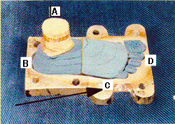
- A. Wooden malleolar block.
- B. Heel block made of sponge rubber.
- C. Metatarsal block made of sponge rubber.
- D. Toe pieces made of sponge rubber.
The aluminium die of the Jaipur Foot
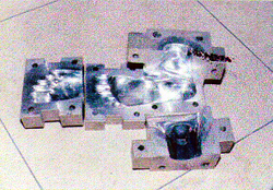
The aluminium die for producing a foot of normal appearance is made in four sections. The sections are bolted together and fit each other perfectly.
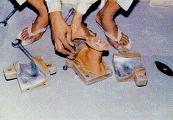
Production process
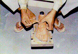
Two patterns of the shape of the sole are cut from the rubber tread compound. The first pattern is placed on the sole portion of the die. A piece of nylon cord 50mm x 350mm is placed on the pattern in such a way that 100mm of it protrudes anteriorly, a part of it covers the sole pattern and rest protrudes posteriorly. The second pattern of the sole is placed on the nylon cord.
The pieces of toes, metatarsal, heel blocks as well as the wooden malleolar block are glued together with vulcanizing solution and applied with one layer of rubber cushion compound. These blocks are placed in the spaces for them over the rubber tread compound pattern. Two strips of nylon cord 50mm x 150mm are placed in between the wooden block and the heel block, and the metatarsal block and heel block. These blocks are then bound with protruding strips of the nylon cord from all sides.
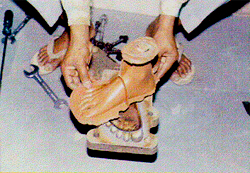
The anterior portion of the nylon cord, which has been divided into five tails, are folded back over each of the toe pieces. The unit is now ready for application of red rubber compound for cosmetic purposes.
The skin coloured red rubber compound is applied to cover the unit from all sides.
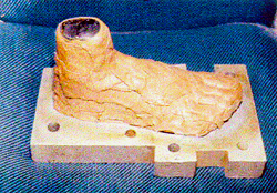
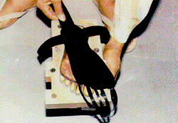
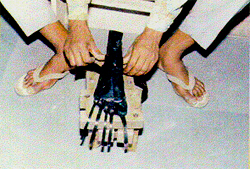
An unvulcanized Jaipur Foot is ready to be packed in the aluminium die.
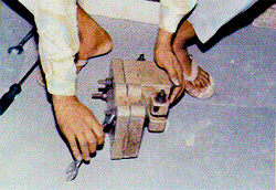
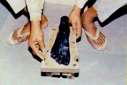
The die is articulated and tightened with bolts. After two hours, the die is opened and foot is inspected for any filling defect. If there are such defects, the gaps are filled with the red rubber compound. The die is again closed and tightened completely.
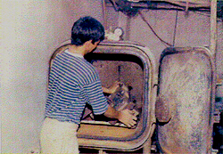
The die is placed in an autoclave and subjected to steam pressure of 158.6 kilopascal at 125 degree celsius for 30 minutes. The die is then removed from the autoclave and allowed to cool.
After the die has cooled, the foot is removed from it.
Vulcanized Jaipur Foot.
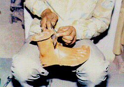
The redundant edges of the red rubber compound are removed and the foot piece is tested with a chrometer for hardness. The Shore hardness should be between 40 A and 60 A all over the foot.
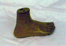
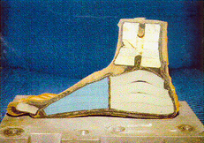
The final shape of the Jaipur Foot.
E. Illustrated notes on making the Jaipur Below-Knee Prosthesis (*4)
The Jaipur below-knee prosthesis is fabricated from high density polyethylene (HDPE) pipes, which are available in the Indian market, and the Jaipur foot.
Main features
- It is a rapid fit limb and its fabrication time is approximately one hour. One limb costs about US$ 25.
- It is functionally and cosmetically close to the natural human limb. Users of this prosthesis can run, squat and sit cross-legged. An active user can climb trees, jump from heights and swim.
- It weighs approximately 1.3 kg.
- No maintenance is required for this limb.
- Barefoot walking is possible; users can work in wet and muddy fields. It can be worn with shoes.
- No formal post-fitment training is required as the adaptation to this limb is instantaneous.
Materials requirement
- HDPE pipe, 600mm to 650mm in length and 90mm in diameter, which is capable of withstanding a pressure of 4 kg per square centimeter.
- Jaipur Foot.
- Leather suspension belt.
- Stockinette tube (3 meters in length).
- Plaster of Paris (POP) impregnated bandages for negative wrap cast.
- Plaster of Paris (POP) powder (3.5 kg).
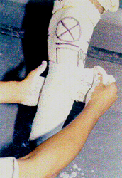
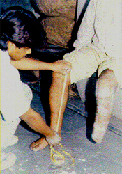
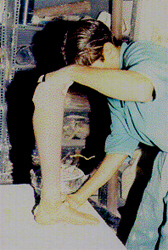
Negative wrap cast
A moistened cast sock is pulled over the stump. The stump is placed in an attitude of flexion. Using indelible pencil, the important features of the stump are marked, such as the outline of the patella, a horizontal line at the mid-patellar tendon, the head of the fibula, the tubercle of tibia, the border of the tibia and the medial and lateral flares. The POP bandage is wrapped around the stump carefully with firm, even tension. Once the cast is hard, the sock is rolled over the stump to remove the cast. Sometimes a small cut behind the knee may be required to remove the cast.
Measurements: remaining leg
The measurements of the sound leg and foot are taken. The length measurement allows construction of a socket of the correct length.
Amputated side
Measurements of the stump length, medio lateral and anteroposterior distances at patellar level are taken.
Modification
An iron rod is inserted in the negative wrap cast to act as a mandrel. The negative cast is filled with a mixture of water and POP. When it has hardened, the bandage is stripped off to yield a positive mould of the stump.
Extension of mould
The mould is extended to a length equal to the length of the sound leg. For this purpose, a cone made of ethaflex sheet (3mm in thickness) is placed over the positive mould and given a 5 degree anterior and 5 degree medial tilt. It is filled with POP paste. When the plaster is hardened, the cone is removed and the extended mould is given the shape of a leg and properly finished. The distal end of the extended mould corresponds to the ankle portion of the Jaipur Foot for proper fit of the socket on the foot.
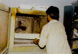
The HDPE pipe is heated in a pre-heated oven for 30 minutes at 180 degree celsius.
The softened pipe is stretched over the mould. Pressure is applied on the weight-bearing areas to make inward bulges and the pipe is rubbed smoothly to remove wrinkles. The pipe is then cooled.
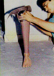
POP is removed from the socket by hammering.
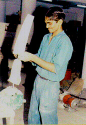
Trimming and finishing
The socket is trimmed and its edges are smoothened to give maximum comfort to the user and allow a range of motion for squatting and sitting cross-legged.
High Density Polyethylene Socket
The HDPE socket is ready for trial.
Main features
- It is a total contact socket with distal end open and made according to the bio-mechanical principles of a patellar tendon bearing (PTB) prosthesis.
- It is a light weight socket and weights about 450gm.
- It is aesthetically acceptable.
Assembling of the Jaipur Foot with socket
The distal end of the socket is heated uniformly from all sides with the help of a heater. When the lower 600 mm of the socket is sufficiently malleable, it is attached to the Jaipur Foot and allowed to cool. After cooling, the distal end of the socket grips the Jaipur Foot tightly. It is further secured with screws.
Suspension belt
A supra condylar suspension belt made of leather is pasted with a hard glue on the socket.
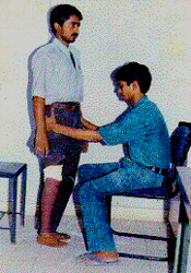
Static alignment
The length of the prosthesis and the static alignment is checked.
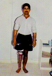
An amputee wearing a Jaipur prosthesis.
F. General maintenance tips for prostheses
Maintanance tips for the care of prostheses include the following:
- Wash the stump daily with soap and warm water. In the initial days the likelihood of irritation is high, so inspect the stump carefully for any abrasion or injury.
- Keep the socket clean from inside by washing and drying it carefully. Do not use detergent to wash the socket.
- Change and wash the sock daily.
- Avoid wrinkles in the sock while it is worn. Wrinkles may cause skin problems.
- As the height of the heel of the shoe is important in establishing alignment, ensure that the height of the heel of the shoe is maintained, and that, whenever a new shoe is used, its heel should be of the same height as that of the original shoe. Consult the prescriber (of the device) if the heel height is different.
- Do not use a prosthesis if any of its components are loose, broken, or worn. Have it replaced as soon as possible.
- If the foot becomes wet, allow it to dry as soon as possible.
- Remove dust, salt, moisture, mud and other contaminants from the prosthesis, especially the knee system and foot-ankle system.
- Carefully examine the socket, shank and foot for cracks. Consult the prescriber (of the device) if cracks are noticed.
- If the socket becomes loose, add additional socks. If no improvement results, consult the prescriber.
- Oil moving parts in the prosthesis, approximately once per week.
G. Nevedac prostheses (*5)
Lower-limb prostheses
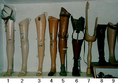
Model 1: A through-hip prosthesis (artificial leg), with a hip joint, knee joint, a sach foot and locking arrangements for the knee and hip joints.
Model 2: An above-knee artificial leg, laminated fibreglass thigh, knee and shin parts and foot with cosmetic toes.
Model 3: An above-knee artificial leg, with a wooden thigh socket, wooden knee and shin pieces, knee lock and a buckle for the pelvic strap; the prosthesis laminated with nylon stockinette for strength and cosmetic finishing.
Model 4: An above-knee artificial leg, laminated fibreglass thigh knee and shin pieces and knee lock.
Model 5: An above-knee artificial leg with aluminium thigh, knee and shin piece, conventional knee joints, padded with felt, leather covering and fitted with a Jaipur Foot.
Model 6: A below-knee artificial leg with thigh corset, laces and conventional knee joints and foot.
Model 7: A Chelsea peg leg for below-knee amputees in the rural areas. This is an old model, no longer in use.
Model 8: A below-knee artificial peg leg, with a rocker base for use in the rural areas/agricultural fields.
Model 9: A P.T.B. (Patellar Tendon Bearing), below-knee artificial leg with a conventional foot.
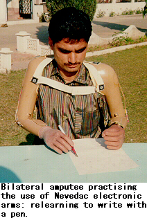
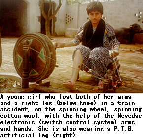
Nevedac electronic arms (*6)
The work of the Nevedac Centre arose out of the demand for prostheses, as a result of amputations from accidents in the use of farm machinery such as threshers and harvesters. Persons affected by polio also use its products.
Through vocational rehabilitation, amputees are trained to become painters, decorators, artists, office workers, and watchmen. About 35 per cent of the Nevedac Centre's employees are persons with disabilities. They mainly do office work. One of them has received a Presidential award for outstanding disabled employee.
Bilateral arm amputees cannot do heavy production work. Their training in the use of prostheses focuses, in the first instance, on using the prostheses to eat, drink, write, as well as undertake activities of daily living, including using the toilet and maintaining personal cleanliness.
The Nevedac electronic arms (switch control system), developed by the Nevedac Centre, have been in use since 1994, with satisfactory results, especially for bilateral arm amputees. These prostheses are easy to operate, as compared with the mechanical arms and hands. The finger operation is also comparatively much easier, more comfortable and smoother.
The Nevedac Centre uses only indigenous raw materials and components, which are easily available within the country. A bilateral arm amputee can be fitted with the electronic arms within a period of 15-20 days, including training in the use of the prostheses.
The Nevedac electronic arms do not require much repair. Usually, only minor adjustments or replacements of the micro switches would be required.
The life of the battery which it uses (packed in a case) is about two years. This is chargeable from the main electricity supply. Each user is given a spare battery, along with a small battery charger, and a spare micro switch, before leaving the Centre.
The cost of this type of prosthesis is Rs. 10,000 to Rs. 13,500 (approximately equivalent to US$300-US$350), plus the costs of travel and board and lodging.
The Centre receives some funding support under a scheme of the Ministry of Welfare, Government of India, for supplying aids and appliances free or at 50 per cent subsidy rate, to low-income persons with disabilities. The cost of assistive devices supplied to State Government employees is reimburseable by their respective Departments. Furthermore, organizations such as the Red Cross, Lion's and Rotary Club provide funding support to needy persons.
H. Summary analyis of prosthetic feet available in Thailand (*7)
This analysis provides an overview of the various prosthetic feet which are produced or which exist in Thailand.
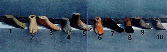
- Khmer Foot (Handicap International)
- Seattle Foot
- Otto Bock Foot or Kingsley Foot
- Thai Rubber Foot
- Nakhon Si Thammarat Foot (NKST)
- Latex Foot (Hancicap International)
- Rubber Foot (Handicap International)
- Chiang Mai Foot
- Lerdsin Foot
- Phra Pra Daeng Foot
In this analysis we look at the technical problems and advantages intrinsic to the various types of artificial feet.
However, this analysis does not apply to the person who wears a prosthetic device which does not allow for correct gait, for example, a prosthesis for which the plaster socket was incorrectly made.
This serves as a reminder that technique directs everything no machine can replace this.
1. The prosthetic foot
It is the point of contact with the ground.
It should:
- Allow for the swing of the pace;
- Absorb any jolts to the heel;
- Not make any noise;
- Be as natural-lookig as possible.
2. List of points to check
The following factors must be taken into consideration:
- Be functional: the foot must correspond with standard performance.
- Be solid: the average lifespan of a prosthetic foot should be between two to three years (as defined by the International Society of Prosthetics and Orthotics, [ISPO]). However, actual lifespan depends on whether it is used as a barefoot or it is used with quality footwear.
- It has to be available at an affordable price, allowing for the provision of this device to the majority of amputees.
- The environment: the social structure, cultural and religious traditions, lifestyle and the climate must all be taken into consideration.
Example:
- The prosthetic foot should be designed in such a way that it is appropriate for wear with sandals (the preferred footwear in Thailand) or sports shoes.
- The foot must also be appropriate to wearing no shoe at all, given the custom of taking off shoes before entering a house.
Analysis
If we were to enter the data from each technical sheet into a computer with the aim of trying to identify those feet which would correspond to the list of points to check, the information given on the right diagram is what we would most likely obtain.
Currently, there is no artificial foot which corresponds to the check list for Thailand
There are several basic reasons for this:
- The feet are not resistant to the tropical climate;
- The feet ae designed for use with shoes with heels; although it should be diagnosed by a prosthetist, unfortunately she/he is usually working under poor conditions. The foot should be designed according to the user's individual lifestyle. Otherwise the result will be poor gait, discomfort and limited durability;
- Walking barefoot destroys the artificial feet.
Conclusion
A good alternative is the Khmer Foot, although it is not perfect and there is room for further improvement. Today the Foot is produced by a local factory with local and quality materials; the work is coordinated and the prosthetists continue to improve on the product.
The Khmer Foot can be produced by a small-scale factory or workshop using appropriate local materials. Work is in progress to enhance the durability of the Khmer Foot.
I. Prescribing and fitting orthoses
The shape of the affected leg of the user is drawn on paper. Locations and heights of various joints are marked on the paper. For example, for an HKAFO (hip knee ankle foot orthosis) the heights of hip bone, crotch, mid-knee and ankle bone are marked. Metal bars are bent suitably to fit the shape of the leg at the bony projections and hinges are provided at the location of various joints to facilitate bending of the leg around the joints. In the AFO, a hinge is placed at the level of the bony lump of the ankle and sometimes at the foot level. The hinge joins the side metal bar with the stirrup which in turn is fitted in the heel of a special shoe.
In the case of KAFO (knee ankle foot orthosis) and HKAFO, the ankle portion remains the same if the hinges at the ankle level are required. KAFO has to be provided hinges at the knee level to allow squatting and sitting. Such a hinge can be locked with a drop lock during walking.
J. Producing a plastic orthosis
Fabrication of a plastic orthosis starts with the making of a hollow plaster cast of the disabled leg(s), making a solid plaster mould thereafter and the heat mould plastic over it.
Take a soft rope and tie a knot at the end of the rope. Put the rope on top of the leg with the knot between the toes, pull a stockinette over the leg and wrap a wet POP bandage over it. After the plaster has become almost firm, cut it along the rope, remove the cast and close the cast before it is fully hard. Put a bent piece of a metallic rod into the hollow cast. Hold the hollow cast in a vertically standing position and fill the cast with a mixture of water and POP. After the plaster is hardened, remove the solid mould. A heated plastic sheet is draped over the solid mould and once the sheet is hardened it is removed from the mould by cutting the plastic. The plastic orthosis is then fine tuned with the help of a heat gun or hot soldering iron. Straps are then rivetted at the right places.
K. Illustrated notes on making polypropylene braces (*8)
Materials required
- Polypropylene sheet (300mm x 600 mm x 3mm).
- Plaster of Paris (POP) powder.
- POP bandage.
- Soft rope, 1 meter in length.
- Stockinettes.
- Metal rod.
- Indelible pencil.
- Leather strap and buckle.
Procedure
![]()
1. Tie a knot at the end of a soft rope.
2. Put the rope on top of the leg, for which brace is to be made, with the knot between the toes.
3. Put the stockinette tightly on the leg with the rope inside. (Avoid wrinkles and make sure the rope stays straight).
4. Wrap wet POP bandage (about 3 layers) while someone else holds the foot in a good position. Heel should be covered with several layers.
5. While the plaster is still wet, smooth it gently with moist hands and press the cast gently into all the hollows of the foot.
6. Before the plaster becomes firm, place the foot in exactly the position that you want the brace to hold it in.
7. Draw some lines over the front of the cast.
8. When the cast is almost firm but still damp (usually in 5 to 10 minutes), cut through the plaster over the rope.
9. Then gently remove the cast, close the cast quickly along the lines you drew and tie it shut with cloth or string.
10. Put a bent piece of rod into the hollow cast.
11. Hold the cast in a standing position.
12. Mix POP and water and quickly poor the mix into the cast to fill all spaces inside the hollow cast.
13. Hold the rod until the plaster is firm.
14. After the POP hardens fully (about one hour), remove the solid mould.
15. Smooth in surface with a file, piece of wire screen or a piece of broken glass.
16. Put the rod of the plaster mould into the pipe of the vacuum machine. Be sure it is very tight.
17. Stretch a stockinette tightly over the cast and tape it to the pipe.
18. Sprinkle dry POP powder over the entire leg and smooth it with your finger.
19. Take a large enough sheet of polypropylene to stretch around the entire mould. Put it into the oven to heat. Once the sheet appears clear, it is ready to be stretched.
20. To remove the hot plastic sheet from the oven, two persons are needed. Each should wear thick gloves. Sprinkle dry POP or talcum powder on the gloves.
21. Lift the sheet by its 4 corners and quickly stretch over the whole solid plaster mould.
22. Quickly pinch the edges of the plastic together along the bottom side of the leg and around the pipe. Work quickly to complete the sealing before the plastic becomes cool.
23. While the plastic is still hot and soft, cut off the extra material with a sharp knife. Switch on the vacuum machine. The plastic will become very close to the mould.
24. After it cools, draw the form of the brace on the plastic.
25. Cut the plastic according to the shape drawn with a cast cutter. It can also be done with a hammer and a chisel.
26. When cool, trim and smoothen the edges of the brace.
27. Glue or rivet a strap near the top of the brace.
- For night use, add 1 or 2 more straps at the ankle and foot.
- For day use, or use with sandal or shoes, only the upper strap is needed.
L. Illustrated notes on making a foot-drop splint (*9)
It prevents dragging of feet in patients with paralysis of dorsiflexors of foot
Materials needed
- Strip of thick cloth or canvas: 50mm broad and 1.5 meter long.
- A rubber tube, elastic or spring-length 70mm.
- Pins.
- Needle, thread and scissors.
- Pair of canvas shoes, or sandals.
Steps
1. Measure the circumference of the thigh 3 fingers above the knee and add 80mm to it. Cut the 'A' canvas piece accordingly.
2. Measure the circumference of the calf three fingers below the knee and add 80mm to it and cut another piece 'B' of canvas.
3. Cut lengthwise remaining piece of canvas into two, leaving 20mm at the end.
4. Stitch the rubber tube, elastic or spring piece to the intact end of the narrow strip so that it makes a Y shape.
5. Stitch or attach end of the elastic/tube/spring to the footwear at position of the forefoot as shown in the figure.
M. Illustrated notes on making a Mukti limb (*10)
Using initial know-how provided by Bhagwan Mahaveer Vikalang Sahayata Samithi of Jaipur, MUKTI adapted modern technology to make limbs which are much lighter, more flexible and at the same time, strong. In terms of cost, Mukti limbs are 3 to 4 times cheaper than those available in general.
MUKTI has developed a new knee-joint with excellent spring action. The conventional knee-joint is rigid and has to be manually locked or unlocked everytime the knee is to be bent. With the MUKTI knee-joint, the person can move normally. The MUKTI knee-joint is effective and easily affordable.
The technology for making artificial hands (upper prostheses) is similar to that of artificial legs (lower prostheses). The rubberized hand which MUKTI is presently getting from ALIMCO, Kanpur, and arm portion are made out of resin instead of HDPE pipes because resin is lighter in weight than HDPE pipes. A leg needs sturdy material to hold the whole weight of the body whereas the hand needs less sturdy material.
With the simple operating system devised by ALIMCO, Kanpur, a hand can function.
MUKTI gets 4 sizes of kit from Kanpur which in turn is used according to the size of the user.
MUKTI limbs have enabled hitherto handicapped persons to run, jump, climb and pedal as well as non-disabled persons at sports meets. Some of the disabled participants performed acrobatics which could prove difficult for any one. MUKTI limbs are so flexible that the users can also swim, hold things and eat comfortably.
MUKTI is continuously undertaking research to further increase the utility of its limbs to users, while keeping the cost-factor the same, so that they are always affordable. As Mukti limbs are fitted free, the lower the cost, the more perons may be given their benefit.
|
|
|
|
|
|
|
|
|
|
|
|
|
|
|
|
|
|
*1 Source: David Werner, Nothing about Us without Us: Developing Innovative Technologies for, by and With Disabled Persons. HealthWrights (1998), Palo, Alto, California, U.S.A.
*2 Source: Bhagwan Mahaveer Viklang Sahayta Samiti, Swai Man Singh Hospital, Jaipur 302004, Rajasthan, India.
*3 At the February 1997 Indian Rupee US dollar exchange rate.
*4 Source: Bhagwan Mahaveer Viklang Sahayta Samiti, Swai Man Singh Hospital, Jaipur 302004, Rajasthan, India.
*5 Source: Colonel D.S. Vohra, Director, NEVEDAC Prosthetic Centre, NEVEDAC Estate, Daulatsinghwala, 104, Sector 11-A, Chandigarh, India. Fax: 91-172-653937; 546489; 547525. Tel: 91-172-653937; 880337.
*6 Source: Colonel D.S. Vohra, Director, NEVEDAC Prosthetic Centre, NEVEDAC Estate, Daulatsinghwala, 104, Sector 11-A, Chandigarh, India. Fax: 91-172-653937; 546489; 547525. Tel: 91-172-653937; 880337.
*7 Source: Report (August 1995) prepared by Mr. Yann Drouet, Prosthetic/Orthotic Expert, Handicap-International Thailand, for the Sirindhorn National Medical Rehabilitation Centre, Soi Bamrajnaradool, Tivanon Road, Amphur Muang, Nonthaburi 11000, Thailand.
*8 Source: David Werner, Disabled Village Children: A Guide for Community Health Workers, Rehabilitation Workers, and Families, The Hesperian Foundation, 1987, see pp. 554-557; David Werner, HealthWrights, 964 Hamilton Avenue, Palo Alto, CA 94301, U.S.A.
*9 Source: "Manual on Community Based Rehabilitation, DRC Scheme", Ministry of Welfare, Government of India, c/o Joint Secretary (Handicap Welfare), Shastri Bhawan, New Delhi 110001, India.
*10 Source: Ms. Meena Dadah, MUKTI, 1 Station Road, Meenambakkam Chennai-600027 Tamil Nadu. Tel. 2346973
Go back to the Contents
ECONOMIC AND SOCIAL COMMISSION FOR ASIA AND THE PACIFIC
Production and distribution of assistive devices for people with disabilities: Supplement3
- Chapter 1 -
ST/ESCAP/1774
UNITED NATIONS PUBLICATION
Sales No. E.98.II.F.7
Copyright © United Nations 1997
ISBN: 92-1-119775-9