Other Devices for People with Mobility Difficulties
A. Illustrated notes on making a crutch (*1)
These guidelines are for making a crutch of the following size:
| Upright | 1,100mm |
| Flat part | 130mm |
| Bending level (from top of the upright) |
500mm |
| Adjustable part | 350mm |
| Maximum height | 1,350mm |
Materials required
- PVC pipe: Use 25mm high pressure pipe (15kg/square centimeter).
- Wood: One piece 200mm x 50mm x 40mm for the axillary support. A round rod with a length of 200 cm and diameter of 20mm diameter.
- Bolts: 1 x 150mm, 8mm diameter. 2 x 80mm, 6mm diameter.
- Thermorex (plastic sponge): Thin layer, 140mm x 220mm.
- Rexin (leatherette): 180mm x 350mm.
- Piece of used tyre for the crutch tip.
- Small nails.
- Adhesive solution (neoprene contact glue).
Tools
- File.
- Hacksaw.
- Drilling machine.
- Cloth buffing wheel.
- Blow lamp.
- Scissors.
- Drill bits: 25mm, 8mm, 6mm.
Step 1:
Axillary support
- Shape the piece of wood as shown in Figure 1-1 (200m x 50mm x 40mm).
- Drill two holes of 25mm diameter as shown in Figures 1-2 and 1-3 to get the final shape as shown in Figure 1-4.
Step 2: Adjustable part
 Cut a piece of PVC Pipe: 350mm long, with a diameter of 25mm.
- Insert a small piece of round wooden rod (20mm diameter).(See Figure 2-1.)
- Drill a hole of 6mm diameter, 30mm from the lower extremity.
 Fix the pipe into a metallic guide with a screw, and drill all the other 20mm holes.(See Figure 2-2.)
 Cut a round piece of tyre (30mm diameter), and nail it to the bottom.(See Figure 2-3.)
Step 3: The uprights
 Flatten a 130mm length at the bottom of the uprights by heating and pressing it on another 25mm pipe. Bend them both to the same angle.(See Figure 3-1)
 On the flat parts, drill two holes (6mm diameter), the first hole, 30mm from the end, the second, 60mm from the first one.
- Fix the adjustable part to the uprights with two flat head bolts.(See Figure 3-2)
 Heat the junction where the two uprights meet. Once the uprights become flexible, place the crutch on the pattern. Place a 150mm piece of wood between the top ends of the uprights and cool the heated part.(See Figure 3-3)
 Trace the level at which the uprights should be bent, i.e., 500mm from the top.(See Figure 3-4)
 Use the pattern to bend the pipe for the handle 500mm from the top. Heat the external side of each upright at the same time, and fix them on the board.(See Figure 3-5)
- Place on a 100mm piece of wood between the top ends of the crutch and another 100mm piece of wood just above the heated parts. Press the uprights towards each other by placing your hands between the 2 pieces of wood and cool the heated parts.
Step 4: Handle
 Cut one 110mm length of pipe
- Insert two small (30mm) round wooden rods into the extremities and fix them with small nails.(See Figure 4-1.)
- Drill a 8mm hole through the centre of the wooden rod.
 Curve both ends of the pipe with a file, so that they fit correctly against the uprights.(See Figure 4-2.)
Step 5: Fitting the handle
 Drill three 8mm diameter holes, 25mm apart from each other, on each upright.
- Fix the handle with the 8mm bolt. (see measurement of the hand level).
Step 6: Fitting the axillary support
 Insert two pieces of wooden rod 30mm in length into the top of the uprights. Nail them through the side of the PVC.
- Fix the axillary support on the uprights with small nails, after checking that the whole crutch is not twisted.
- Cover the axillary support with a thin layer of foam sponge and then with supple rexine, using adhesive solution.
Note: Wait at least 10 minutes for the adhesive solution to dry before sticking the foam sponge. Use the same procedure when sticking rexine on to the foam sponge.
B. Illustrated notes on making a simple hand grip (*2)
Hand grips can help a disabled person to hold many things
Hand grips can be made of:
- Clay (modelling clay or clay from the ground)
- Plaster (plaster of Paris or plaster used for building)
Clay and plaster can usually be obtained locally, either free or at low cost. They are heavy and can be fragile. To make them stronger, chop up pieces of string and add them to the mixture. Epoxy resin putty is more expensive but it is the strongest and lightest material and can be immersed (placed or soaked) in water. - Epoxy resin putty (a synthetic substance. Several brands are available, including Modulan: This is made by Ciba-Geigy and in some countries is known by other names.)
- Handlebar grips for bicycles and motorcycles
- Film canisters.
Empty film canisters can be obtained free of charge at most shops where film is developed.
Using film canisters
 Cut the canister lid with scissors. The small cuts around the main cut are important as the container lid grips the item placed inside. Make a small hole in the base of the canister.
 Thread a piece of ribbon or elastic into the two holes.
 Place the item (e.g. spoon) into the hole in the lid and make sure it is firmly in place in the canister. The twisted spoon shown here is for use by someone who cannot turn her/his wrist.
- Tie the ribbon or elastic to close around the hand firmly but not too tightly. Alternatively, sew small pieces of velcro to the ends of the ribbon.
Using clay, plaster or putty
- Take a small piece of the material and make it into a ball.
- Put the ball into the hand which the person feels most comfortable using.
- Put the item on which the grip is to be fixed, such as a tool, into the material in the hand. With items such as pencils and forks, push the end of the item through the material. Do not wrap the material around the item.
- Make the person hold the item in the way he or she would normally use it.
- Press the person's holding parts of the hand firmly in position so that a clear impression is made.
- Leave the material in the person's hand for three or four minutes. Then take the item which is to become the grip out of the hand and let it harden. (If the person feels very uncomfortable during this process, remove the material carefully.)
- If the grip is made of clay, bake it in the sun. Cover with oil or grease to make it more resistant to water. Do not place the clay grip in water if you are washing the item.
C. Illustrated notes on making a stick reacher (*3)
A. Aluminium reacher
Materials Required
- Aluminium tube, 15mm diameter.
- Thick aluminium wire, 350mm long and 4mm in diameter.
- Thin wire, 400mm long.
- Vinyl tape.
Procedure
- Cut the aluminium tube to an appropriate length (according to purpose and needs of the user).
 At one end, drill two holes through the tube. The hole size should match the diameter of the thin wire. Drill another hole of 4mm diameter, 30mm below the two holes.
 Put the thick wire through the lower hole, and bend into an appropriate shape according to the intended use.
 Put the thin wire through the upper set of holes. Attach the thick wire firmly to the tube by winding the thin wire around it were.
- Wind Vinyl tape over the thin wire.
Note: The total length of the reacher is determined by individual need, but a length between 500mm and 700mm is generally appropriate.
D. Illustrated notes on making a panty-type urinal kit (*4)
Materials
The parts needed for assembling the kit:
- Woman's panty.
- Tube type rubber penile container having several shallow folds similar to bellows (diameter of the proximal hole is 35mm).
- Proximal amber rubber tube (the inside diameter is 8mm and the length is 25cm).
- Another distal rubber tube (the inside diameter is 6mm and the length is 30cm).
- Bag to collect urine.
- Hard plastic ring (the inside diameter is 40mm, the outside diameter is 45mm, the outside diameter at each hem is 48mm and the height is 20mm).
- Condom.
- Plastic clamp.
- Biased woven tape.
- Rubber string.
- Vinyl tape
- Three pairs of plastic connection tubes with screw inside.
Steps
- Cut and make a hole in a panty, accurately just as wide as the inside area of the plastic ring with a diameter of 40mm at the place just below the front seam.
- Stitch the bias tape around the fringe and fix it firmly to the panty.
- Make the rubber string run through the stitched bias tape around the fringe.
- The tube part of the rubber penile container is to be made 30mm long at the distal end, and set the plastic connection screw tube.
- Turn back the rubber penile container from inside of the ring and fix to the outside of the plastic ring.
- Cut the tip of the prominent part of the condom to the proper dimension depending on each user's size. Then turn back the condom from inside of the ring and fix to the plastic ring on the penile container.
- Fix the above described component tightly to the cut fringe of the hole of the panty.
- Cut the proximal rubber tube to the exact length of the client's upper thigh in order to avoid instability of the tube during his routine movement, and set the plastic connection screw tube.
- Connect the urine-collection bag to the above rubber tube with plastic connection tube.
- Cut a Velcro fastener to the proper length for use as a belt to fix the urine collection bag.
- Bias tape ring for disabled fingers can be set to the four ends of the urine bag belt.
- Connect the urine-collection bag to the proximal tube.
- Connect the distal tube to the collection bag.
- Roll vinyl tape to the tube just described above at 5cm under the plastic connection tube.
- Set the plastic clamp over the taped rubber tube.
- Ring for the disabled fingers can be set at upper part of the back of the panty. The assembled kit is now ready for use.
Result (*5)
A C-6 spinal cord-injured man with only C-7 ability (presented by the triceps strength with poor level on the MMT) achieved putting on and taking off the panty-type urinal kit independently. He is able to connect and disconnect every junction of the assembly and empty the urine bag and perform all other actions to handle this type of urinal kit with tenodesis action of his wrists. The basic position to put on and take off the panty type urinal kit for him is supine.
Spinal cord-injured persons have fewer urinary problems after using this kit. Some of them do not need hooks for assistance and use tenodesis motion only. Many lower spinal cord-injured people use this kit, having changed from using conventional ones.
Source: Self-help Devices for the Physically Disabled, p. 8, Japan Sun Information Center (1987).
E. Design of a swivel spoon (*6)
F. Design of a pronged-handle spoon (*6)
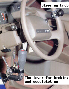
G. Hand-control Driving System (*7)
A hand-control driving system enables persons with locomotor disabilities to drive a car safely using both arms. Users of this system include persons with paraplegia, quadriplegia and others who have some arm strength to rotate with one arm the steering wheel, while using the other arm to push and pull a lever for braking and accelerating purposes. For this purpose, the vehicle must have automatic transmission, preferably with power steering.
Such a device would expand employment and self-help opportunities for people with locomotor disabilities.
Variations of such a system are being developed by people with disabilities for use in the developing countries of the region.
*1 Source: Handicap International, Ave. Berthelot 14, 69007 Lyon, France
*2 Source: CBR News, No. 16, January-April 1994, AHRTAG 1 London Bridge Street, London SE1 9SG, UK.
*3 Source: Self-help Devices for the Physically Disabled, Sun Information Center, Japan, 302 Urban Bldg. 2-23 Shinjuku 4-chome, Shinjuku-ku, Tokyo 160, Japan.
*4 Source: Self-help Devices for the Physically Disabled, Sun Information Center, Japan, 302 Urban Bldg. 2-23 Shinjuku 4-chome, Shinjuku-ku, Tokyo 160, Japan.
*5 Source: Self-help Devices for the Physically Disabled, p.8, Japan Sun Information Center (1987).
*6 Source: Indian Institute of Technology, New Delhi, Hauz Khas, New Delhi 110016, India, Fax: 91-11-6862037.
*7 Source: Auto Perfect Drive, Nissin Jidosha Kogyo Co. Ltd. Tel: 0480-72-7221, Fax: 0480-72-7223, 1-563-12 Toyonodai Ohtonemachi, Kitasaitama-Gun, Saitama, 349 Japan.
Go back to the Contents
ECONOMIC AND SOCIAL COMMISSION FOR ASIA AND THE PACIFIC
Production and distribution of assistive devices for people with disabilities: Supplement3
- Chapter 3 -
ST/ESCAP/1774
UNITED NATIONS PUBLICATION
Sales No. E.98.II.F.7
Copyright c United Nations 1997
ISBN: 92-1-119775-9